

Please Leave Us A Message
Privacy statement: Your privacy is very important to Us. Our company promises not to disclose your personal information to any external company with out your explicit permission.
2023-02-07
Encoder and Application Overview
The encoder is an electromechanical device that can be used to measure mechanical motion or target position. Most encoders use optical sensors to provide electrical signals in the form of pulse trains, which in turn can be converted into motion, direction, or position information.
Rotary encoders can be used to measure the rotational movement of the shaft. Figure 1 shows the basic components of a Rotary Encoder, including a light emitting diode (LED), a code wheel, and a light Sensor on the back of the code wheel. This code wheel is placed on a rotating shaft with opaque and light-transmitting fan-shaped areas arranged in an encoded form. When the code wheel rotates, the opaque sectors block light, and the light-transmitting sectors allow light to pass through. This produces square-wave pulses that can be compiled into corresponding position or motion information. The encoder is usually divided into 100 to 6000 sectors per revolution. This shows that a 100-sector encoder can provide 3.6 degree accuracy while a 6000-sector encoder can provide 0.06 degree accuracy.
Linear encoders work like rotary encoders. It uses a fixed, opaque strip to replace the rotary encoder, with some light-transmissive gaps on the opaque strip surface, and the LED detector assembly is attached to the moving body.

Figure 1. Components of an optical encoder
Only one pulse output encoder cannot determine the rotation angle, so it is not useful. If two code channels are used, and the phase difference between their sectors is 90 degrees (as shown in FIG. 2), the two output channels of the quadrature encoder can determine the two information of position and rotation direction. For example, if channel A leads the phase, the encoder rotates clockwise. If channel B leads the phase, then the code wheel rotates counterclockwise. Therefore, by monitoring the number of pulses and the relative phase information between the signals A, B, it is possible to obtain the position and direction information of the rotation at the same time.
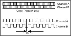
Figure 2. Output signals of quadrature encoders A and B
In addition, some quadrature encoders also include a third output channel called zero signal or reference signal. A single pulse is output for each rotation of this channel. You can use this single pulse to accurately calculate a reference position. In most encoders, this signal is called Z axis or index.
So far, this article introduced a single-ended incremental quadrature encoder. Because both A and B signals are referenced to ground, they are called single-ended and each signal has only one (or only one) line. Another commonly used encoder is a differential encoder, and its A and B signals have two wires. The two lines of the A signal are A' and A, and the two lines of the B signal are B' and B, respectively. Because these four lines always output a known level (0V or Vcc), this structure is also called a push-pull structure. When A is Vcc, A' is 0V. Conversely, when A is 0V, A' is Vcc. In the case of a single-ended encoder, A is either Vcc or floating. Using differential detection can ensure the accuracy of the signal, so differential encoders can usually be used in environments with large electrical noise.
With an Incremental Encoder, only position change information (from which motion speed and acceleration can be calculated) can be measured, but the absolute position of the target cannot be determined. Here, we will introduce a third type of encoder: Absolute Encoder, which can obtain the absolute position of the target. This encoder, like the incremental encoder, has alternating opaque sectors and transparent sectors. However, an absolute encoder uses a multi-component zone on the code wheel of the encoder to form a concentric code channel, just like a target ring. The concentric code path starts from the center of the encoder code and extends outward until the outside of the code board. Each code channel has twice the partition than its inner layer. The first layer, the innermost code channel, has only one light-transmitting sector and one opaque sector; the second layer at the center has two light-transmitting sectors and two opaque sectors; and There are four light-transmitting sectors and opaque sectors for the third code channel. If the encoder has 10 layer code channels, then the outermost code channel has 512 sectors; if there are 16 layer code channels, then the outermost code channel has 32,767 sectors.
Because the absolute encoder has more than one number of sectors per code channel than the one inside it, the number of sectors forms a binary counting system. In this type of encoder, each code channel on the code wheel corresponds to a light source and a receiver. This means that a 10-layer encoder requires 10 groups of light sources and receivers, while a 16-layer encoder requires 16 groups of light sources and receivers.
The advantage of an absolute encoder is that you can reduce the speed of the encoder and make the coder of the encoder make only one revolution during the entire machine motion cycle. If the machine travels 10 inches and the encoder has 16 bits of precision, then the accuracy of the machine position is 10/65,536, or 0.00015 inches. If the machine travels longer, such as 6 feet, then a coarse rotary encoder can ensure that each foot is tracked; a second stage, called a fine rotary encoder, can track distances within 1 foot. This means that you can adjust the coarse encoder so that it rotates around the entire 6-foot distance; you can also adjust the thin encoder so that it can resolve a range of 1 foot (or 12 inches).
How to measure using an encoder
To use an encoder for measurement, there must be a basic electronic device, the counter. The basic counter generates a value through its several input channels to indicate the number of detected edges (ie changes from low to high or high to low in the waveform). Most counters have three interrelated inputs-threshold, source, and up/down selection. The counter records the number of events in the source input and counts up or down according to the state of the up/down selection line. For example: if the up/down status bit is "high" then the counter counts up; if the up/down status bit is "low" then the counter counts down. Figure 3 shows a simplified counter block diagram.

Figure 3. Simplified model of the counter
Encoders usually have 5 wires that need to be connected. Different encoders, the color of these lines is not the same. You can use these wires to power the encoder and read A, B, and Z signals. Figure 4 shows a typical interface definition for an incremental encoder.

Figure 4. Incremental encoder interface
The next step is to decide where these lines should be connected. As mentioned above, the signal A is connected to the source terminal and the pulses in its signal are counted. Signal B is connected to the up/down selection port. Connect any +5V DC power supply to the power and ground connections-in most cases, only one digital line for a data acquisition device is sufficient.
Since the signal edges are counted, the next thing you need to consider is how these values should be converted into position information. The process of converting the edge value into position information depends on the type of encoding used. There are three basic types of encoding: X1, X2, and X4.
X1 encoding
Figure 5 shows the number of plus-minus counts for a quadrature period and its corresponding X1 encoding type. When channel A leads channel B, the increment occurs on the rising edge of channel A. When channel B leads channel A, the decrement occurs at the falling edge of channel A.
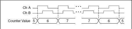
Figure 5. X1 encoding
X2 encoding
The X2 encoding is similar to the above process, except that each edge count of the counter A channel is incremented or decremented, depending on which channel is being channeled. The value of the counter will increase by 2 or decrease by 2 each cycle, as shown in Figure 6.

Figure 6. X2 encoding
X4 encoding
In the X4 coding mode, the counter also increases or decreases on each edge of the channels A and B. Whether the number of counters increases or decreases depends on which channel leads which channel. The number of counters will increase by 4 or decrease by 4 every cycle.
Once you have set the encoding type and pulse count type, you can use the following formula to convert numeric information to position information:
For rotation position
Rotation amount ![]()
Where N = number of pulses generated by the encoder during each rotation of the shaft
x = encoding type
For linear position
Displacement ![]()
Where PPI = pulse per inch (this parameter relates to the selected encoder)
Connecting the Encoder to the Instrument
In this section, take the NI cDAQ-9172 chassis and the NI 9401 C Series digital I/O module as an example. Using different measuring instruments and equipment is similar to this process.
Equipment used:
cDAQ-9172 : NI CompactDAQ 8-Slot Hi-Speed USB Chassis
NI 9401: 8-Channel, 5 V/TTL High Speed, Bidirectional Digital I/O Module
24 pulse/rotation quadrature encoder
The NI 9401 has a D-Sub connector that provides connectivity for 8 digital channels. Each channel has a digital I/O port that can be connected to a digital input or output device. Only through the 5th and 6th slots on the chassis can you connect to the two counters in the cDAQ-9172; therefore, insert the 9401 into the 5th slot.
According to these specifications, connection A on the encoder is connected to pin 14 and connection B is connected to pin 17 and "5 VDC Power" is connected to any unused digit line set to "high". " "Connect to any COM port.
Start measuring
Now that the encoder has been connected to the measurement device, you can use NI LabVIEW graphical programming software to transfer this data to a computer for observation and analysis.
Excerpt from: NI "General Measurement Guide"
Share to:
Send Inquiry

Ms. carol Dong
Tel:86-431-85543703
Fax:86-431---88634119
Mobile Phone:+8613894866263
Email:sales@encoders.com.cn
Address:333Feiyue Donglu, Changchun City, Jilin Province. China, Changchun, Jilin
Related Products List
Mobile Site
Privacy statement: Your privacy is very important to Us. Our company promises not to disclose your personal information to any external company with out your explicit permission.
Fill in more information so that we can get in touch with you faster
Privacy statement: Your privacy is very important to Us. Our company promises not to disclose your personal information to any external company with out your explicit permission.